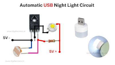
So Hey guys in today's article I am going to teach you how to make a LDR circuit.
Introduction:
An LDR circuit uses an LDR to detect changes in ambient light levels. It is made up of an LDR, a resistor, and a load, and can be used to turn on or off a load when the ambient light level falls below or rises above a certain threshold. LDR circuits are easy to build and can be used in a variety of applications, such as automatic night lights and light-sensitive alarm circuits.By using the some basic components I am going to make the LDR circuit components we need for making this circuit.
- BD139
- 3.3K Resistor
- LDR
- 3.7V LED
- 5V Power Supply (You can use powered supply)
The BD139 transistor is used in the circuit as a switch that turns on and off the LED light. The LDR, or light-dependent resistor, is used to detect changes in ambient light levels. When the ambient light level falls below a certain threshold, the resistance of the LDR decreases, allowing current to flow through the transistor, turning on the LED light.
Before continue this article is sponsored by JLCPCB Make your next project a reality with JLCPCB! The premier PCB company in China, delivering top-notch 1-8 Layer PCBs starting at only $2 and PCBA at an unbeatable $0 (with free setup and stencil included). Register now using my link and receive a juicy $54 new user coupon code to electrify your creativity! Link : https://jlcpcb.com/IUP
let's continue to our topic Alternatively, a 3.3k resistor can be used instead of an LDR in the circuit. This resistor serves as a voltage divider, allowing the voltage at the base of the transistor to be adjusted according to the ambient light level. As the ambient light level decreases, the voltage at the base of the transistor decreases, allowing current to flow through the transistor and turning on the LED light.

.gif)
Post a Comment
Post a Comment